EXAMPLE#1 – BASIC MSB:
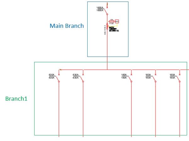
In this example, we received the following SLD to be designed:
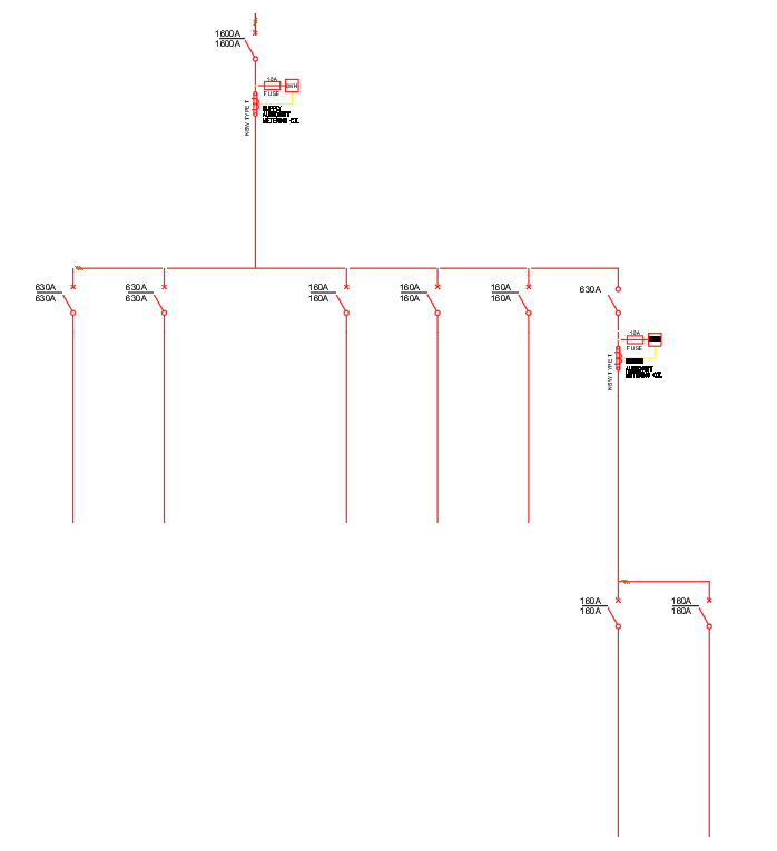
From the SLD electrical connections , we identify the quantity of Branches.
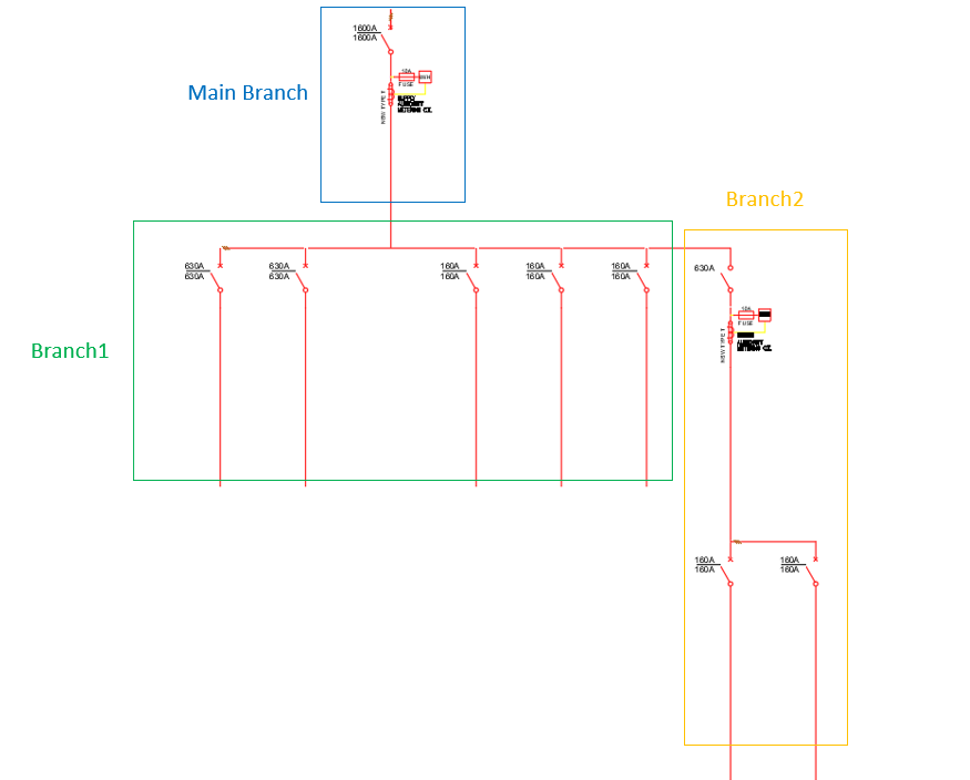
We will need MAIN BRANCH, BRANCH1, and BRANCH2:
1. We proceed to Streamgineer and create a new project. SEE START-A-DESIGN
2. From now onwards, all the selections will be from the Design Parameters.
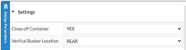
3. We specify the Vertical Busbar Type:
SETTINGS -> VERTICAL BUSBAR LOCATION
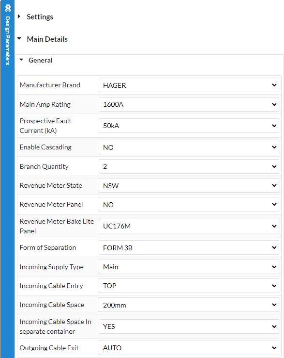
4. Now we select all the relevant parameters for our MAIN BRANCH:
MAIN DETAILS -> GENERAL
The Key Parameters here are:
Main Amp Rating = 1600A
Branch Quantity = 2
Revenue Meter State = NSW
Incoming Supply Type = Main
Incoming Cable Entry = TOP
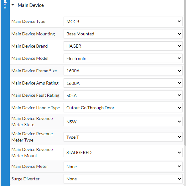
5. Now we select all the relevant parameters for our MAIN Device:
MAIN DETAILS -> GENERAL
The Key Parameters here are:
Main Device Type = MCCB
Main Device Model = Electronic
Main Device Frame Size = 1600A
Main Device Amp Rating = 1600A
Main Device Revenue Meter State = NSW
At this point we have already completed our MAIN BRANCH.
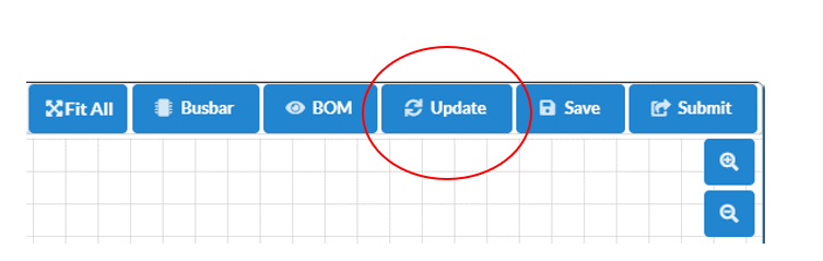
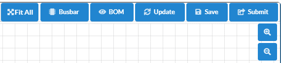
We can verify the design thus far by clicking the UPDATE button on the Top Right:
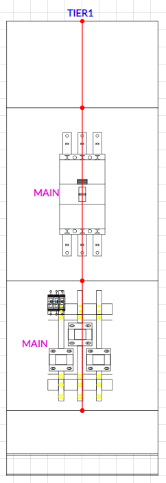
The General Arrangement looks like this so far:
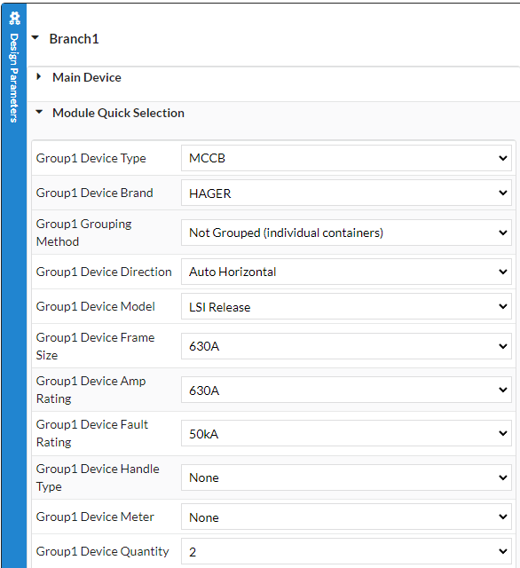
6. Next we select the relevant parameters for BRANCH1:
Let’s have another look at the SLD to see BRANCH1 and refresh our memory:
For BRANCH1 we require the following:
2 x 630A MCCB
3 x 160A MCCB
We can immediately identify we will have two (2) Groups in our branch.
(Group1) – 2 x 630A MCCB
(Group2) – 3 x 160A MCCB
BRANCH1 Main Device is not needed.
6a. Let’s first add our BRANCH1-Group1 components:
BRANCH1 -> MODULE QUICK SELECTION
The Key Parameters here are:
Group1 Device Type = MCCB
Group1 Device Frame Size = 630A
Group1 Device Amp Rating = 630A
Group1 Device Quantity = 2
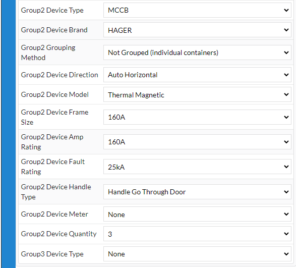
6b. Now let’s add our BRANCH1-Group2 components:
BRANCH1 -> MODULE QUICK SELECTION
The Key Parameters here are:
Group1 Device Type = MCCB
Group1 Device Frame Size = 160A
Group1 Device Amp Rating = 160A
Group1 Device Quantity = 3
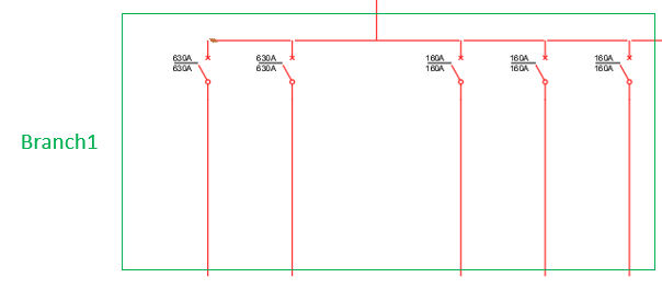
6c. Now let’s UPDATE our design and see what it looks like so far:
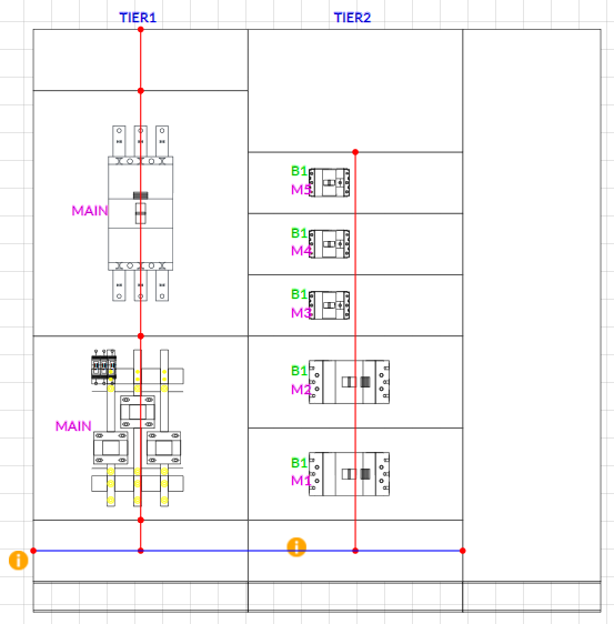
Things are looking pretty good 
So far our SLD looks like this:
7. Next we select the relevant parameters for BRANCH2:
Let’s have another look at the SLD to see BRANCH2 and refresh our memory:
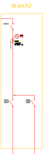
For BRANCH2 we require the following:
1 x 630A ISOLATOR with Revenue Meter
2 x 160A MCCB
We can immediately identify we will need a BRANCH2 Main Device and one (1) Group in our branch.
(Branch2 – Main Device) – 1 x 630A ISOLATOR with Revenue Meter
(Group1) – 2 x 160A MCCB
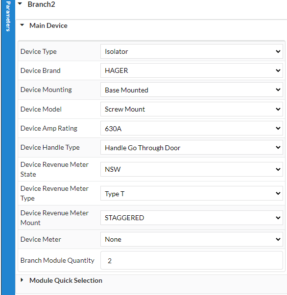
7a. Let’s first add our BRANCH2 Main Device:
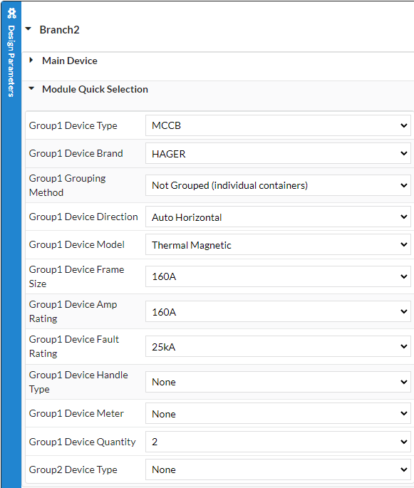
7b. Now let’s add our BRANCH2-Group1 components:
7c. Finally let’s UPDATE and see how things are looking:
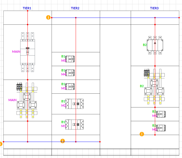
And here’s our SLD:
