OVERVIEW
Streamgineer uses the concept of branches to configure and add all relevant components into the design.
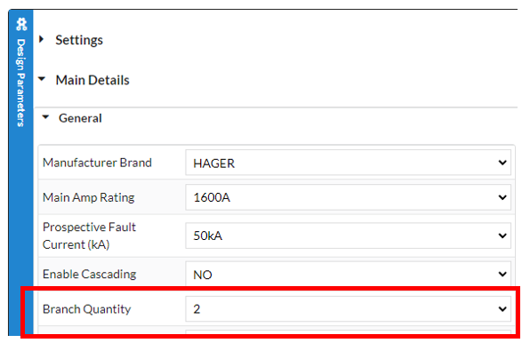
Branches are selected from the Design Parameters section.
You can specify the quantity of Branches required under:
Main Details -> General -> Branch Quantity
Branches and the Modules (Module1,2,3,4,5….11) within a branch can then feed other branches to create a structure that is very similar to an electrical design structure.
If you think of branches in an electrical sense, a typical branch (Branch1,2,3,4,5) has a main component, and this main component in turn feeds other Modules (Module1,2,3,4,5…11) which are then placed in parallel to each other.
The possible branches are:
MAIN Branch: The first and most important Branch and it is always present. This branch only has components in series below it.
GEN Branch: Used for Generator (Gen) devices only and has components in series below it (but it doesn’t need to be present).
BRANCH1: Can have a Branch1 Main Device (but not required), feeding Branch1 Modules (Branch1-Module1,2,3,4,5….11).
BRANCH2: Can have a Branch2 Main Device (but not required), feeding Branch2 Modules (Branch2-Module1,2,3,4,5….11).
BRANCH3: Can have a Branch3 Main Device (but not required), feeding Branch3 Modules (Branch3-Module1,2,3,4,5….11).
BRANCH4: Can have a Branch4 Main Device (but not required), feeding Branch4 Modules (Branch4-Module1,2,3,4,5….11).
BRANCH5: Can have a Branch5 Main Device (but not required), feeding Branch5 Modules (Branch5-Module1,2,3,4,5….11).
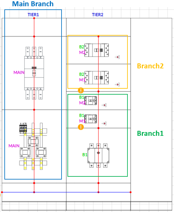
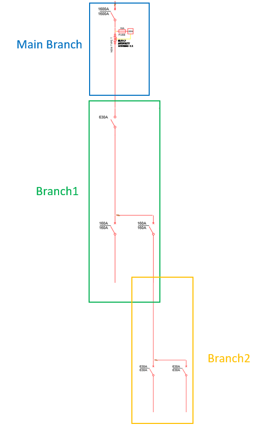
Consider the Single Line Diagram (SLD) of EXAMPLE #1 below:
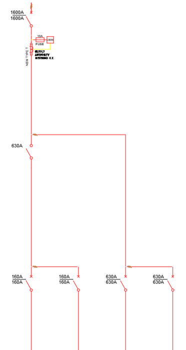
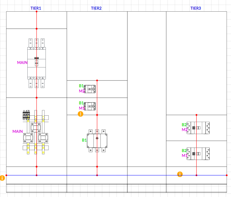
The above SLD has: MAIN Branch, BRANCH1 and BRANCH2.
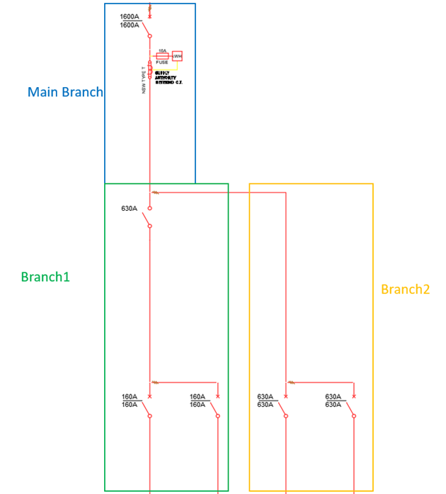
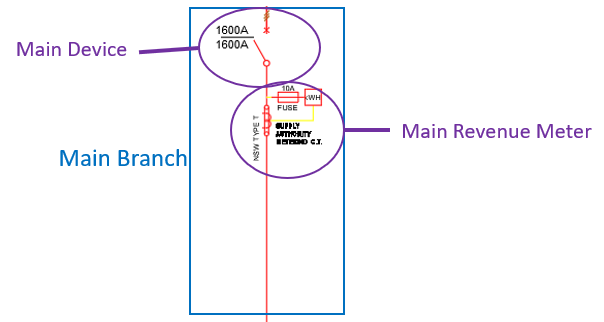
MAIN Branch has:
1 x 1600A ACB (Main Device)
1 x Revenue Meter with fuses (Main Revenue Meter)
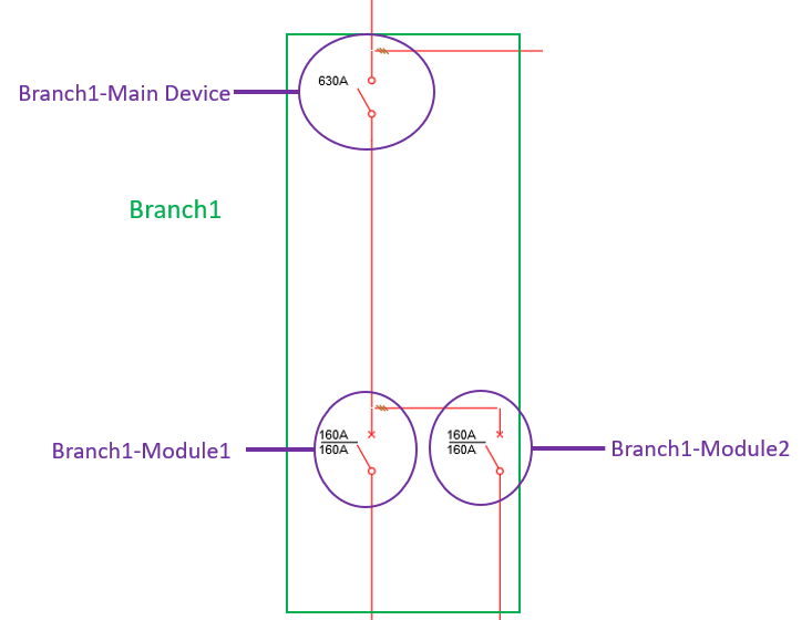
BRANCH1 has:
1 x 630A Isolator (Branch1 Main Device)
1 x 160A MCCB (Branch1-Module1)
1 x 160A MCCB (Branch1-Module2)
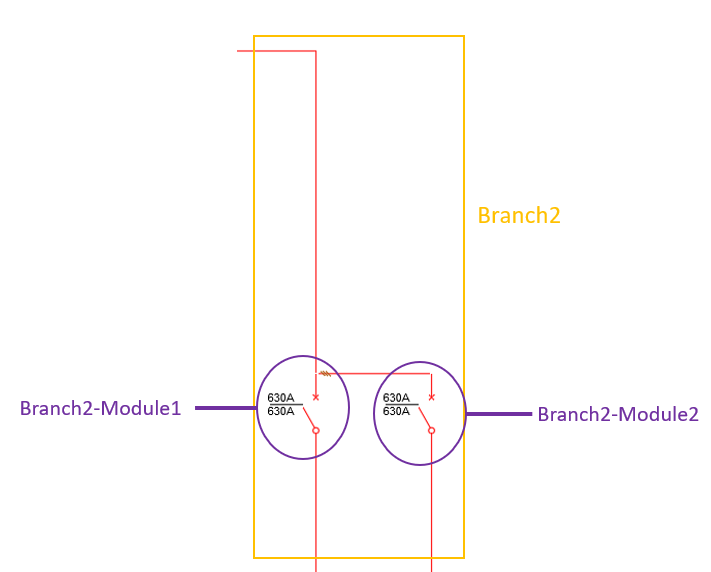
BRANCH2 has:
1 x 630A MCCB (Branch2-Module1)
1 x 630A MCCB (Branch2-Module2)
BRANCH1 and BRANCH2 are fed from MAIN BRANCH.
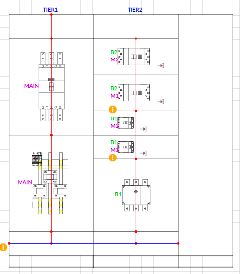
For Example# 1, the General Arrangement looks like this:
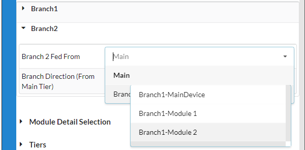
FEED OF BRANCHES
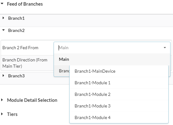
Branches are connected by specifying the relevant Design Parameters on FEED of BRANCHES.
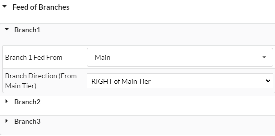
You can specify where the BRANCH is being fed from, as well as the direction (in the general arrangement) you wish the BRANCH to go.
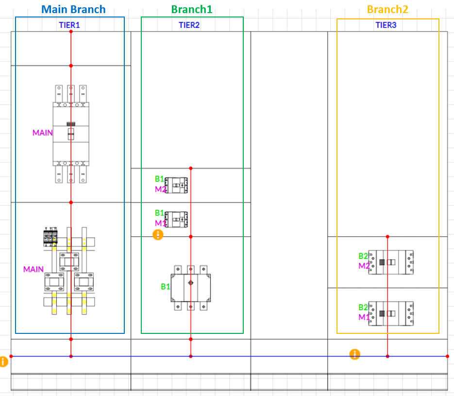
Let’s take another look at Example #1:
Now let’s feed BRANCH2 from BRANCH1-MODULE2 and see the result:
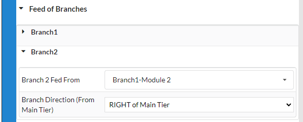
The resulting SLD looks like this:
The resulting GA (General Arrangement) looks like this: